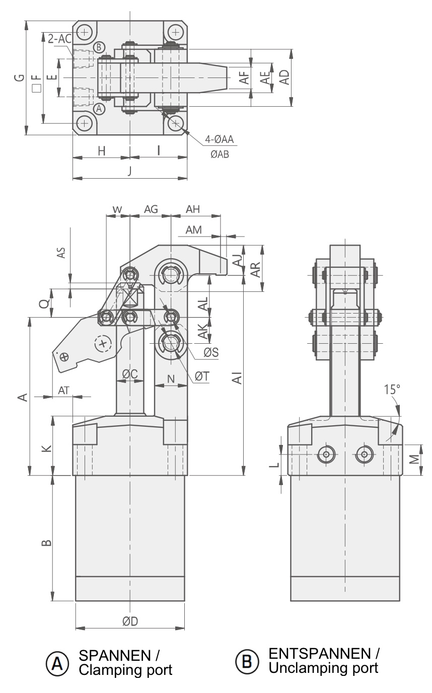
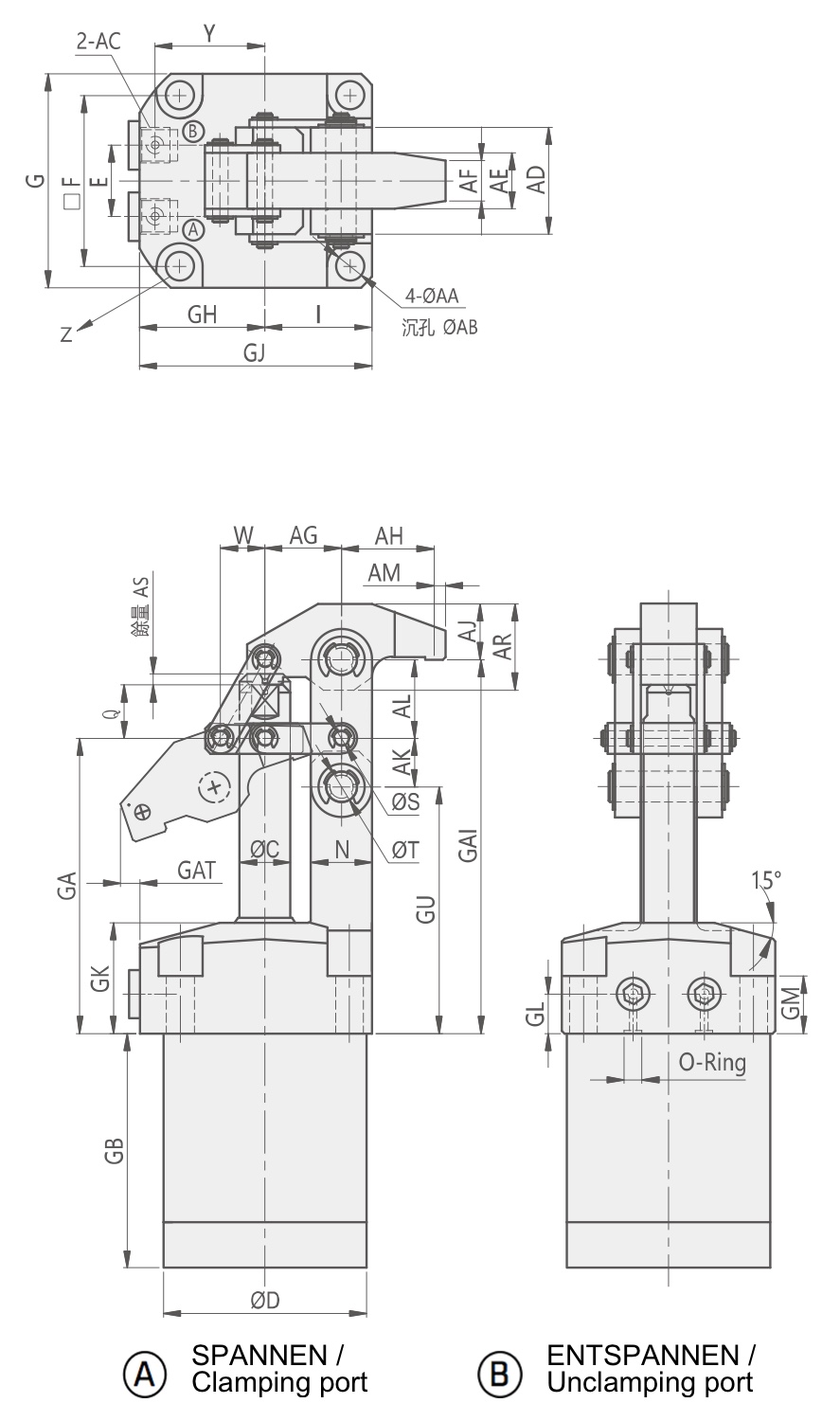
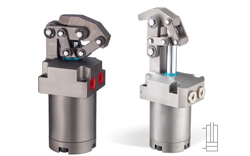
HLS Hydraulic Link Clamp - Hydraulic lever clamp
Hydraulic Link Clamp - Hydraulic Cylinder :
- Designed for high clamping forces with low operating pressure
- Particularly designed to reduce the interference with loading and unloading operation.
- Material cylinder body and clamping arm : C45 steel, nitrated
- Material piston rod : high alloy steel, hardened and tempered
- Manifold piping and G port piping are optional available.
- Clamping forces 2,9kN up to 11,36kN (4 cylinder sizes)
- Complete with lever mechanism and clamping arm
- High-quality seals resistant to chlorine-based cutting fluid and prevent infiltration of cutting chips and dust.
- Min. operating pressure : 10bar
- Max. operating pressure : 70bar
- Range of Temperature : -10 ~ +70°C
- Customized versions are available on request.
➝ CAD-files and prices on Request !
Product Datasheet (Download)Example ordering code:
HLS - 32 G
Series – Cylinder inside diameter – Port type
| ① | SERIES | HLS | |
| ② | Cylinder inside diameter |
25 :Ø25 mm
32 :Ø32 mm 40 :Ø40 mm
50 :Ø50 mm |
|
| ③ | Port type | Blank: Standard Line type (tube type) G: Manifold type (O-ring/Gasket type) |
| Model | Clamping force at 70 bar | Clamping stroke | Total stroke | Oil capacity Clamp | Oil capacity Unclamp | eff. piston area clamp | eff. piston area unclamp | CAD |
|---|---|---|---|---|---|---|---|---|
| [kN] | [mm] | [mm] | [cm³] | [cm³] | [cm²] | [cm²] | ||
| HLS-25 | 2,9 | 31,5 | 34 | 16,69 | 11,46 | 3,37 | 4,91 | |
| HLS-32 | 4,41 | 35,5 | 38 | 30,55 | 25,05 | 6,6 | 8,04 | |
| HLS-40 | 7,09 | 41 | 44 | 55,26 | 46,46 | 10,56 | 12,56 | |
| HLS-50 | 11,36 | 47 | 50 | 98,15 | 82,45 | 16,49 | 19,63 |