PSC Pneumatic Swing Clamp
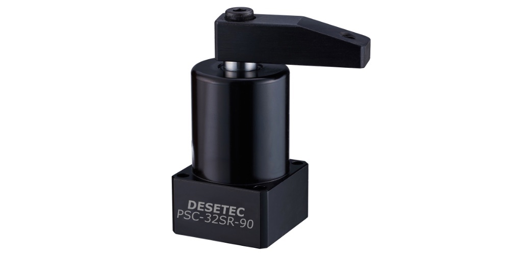
- compact series for use in tight spaces
- Body material: aluminium alloy
- Holding capacity 240N up to 2000N
- lightweight, robust and reliable
- high durability
- complete with clamping arm
- double acting
- Operating pressure : 4 to 7 bar
- Range of Temperature : -10 ~ +60°C
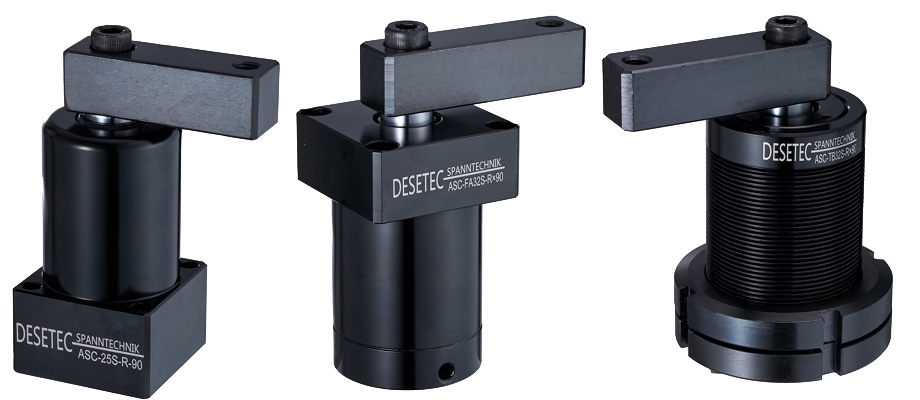
- various mounting and piping types
➝ CAD-files and prices on Request !
Note :
- Filtered and oiled compressed air must be used !
- Customized modifications are possible !
Ordering Indiction : PSC-MF25S-R90
| ① | PSC | Serie | PSC |
|---|---|---|---|
| ② | MF | Mounting and piping types | Blank : Standard Line type M : Manifold piping type MF : Manifold with Flow Control FA : Upper Flange type TB : Threaded body |
| ③ | 25 | Cylinder inside diameter | Φ25, Φ32, Φ40, Φ50, Φ63 (mm) |
| ④ | S | Clamping arm type | S : Single side arm D : Double side arm |
| ⑤ | R | Rotating direction | R : Turn right (clockwise direction) L : Turn left (anti-clockwise direction) N : 0° (No swing) |
| ⑥ | 90 | Rotating angle | Standard angle : 90° (±2°) optional : 45° ±(2°), 60° (±2°) Special angles on request. |
| Model No. | Clamping Force at 7bar [KN] | Swing Stroke [mm] | Clamping Stroke [mm] | TOTAL STROKE [mm] | Cylinder Capacity CLAMP [cm3] | Cylinder Capacity UNCLAMP [cm3] | Eff. Piston Area CLAMP [cm2] | Eff. Piston Area UNCLAMP [cm2] |
|---|---|---|---|---|---|---|---|---|
| PSC-25 | 0,24 | 12 | 12 | 24 | 11,78 | 8,09 | 4,91 | 3,37 |
| PSC-32 | 0,43 | 12 | 12 | 24 | 19,30 | 14,47 | 8,04 | 6,03 |
| PSC-40 | 0,75 | 12 | 12 | 24 | 30,14 | 25,32 | 12,56 | 10,55 |
| PSC-50 | 1,18 | 14 | 14 | 28 | 54,96 | 46,17 | 19,63 | 16,49 |
| PSC-63 | 2,00 | 15 | 15 | 30 | 93,48 | 84,06 | 31,16 | 28,02 |
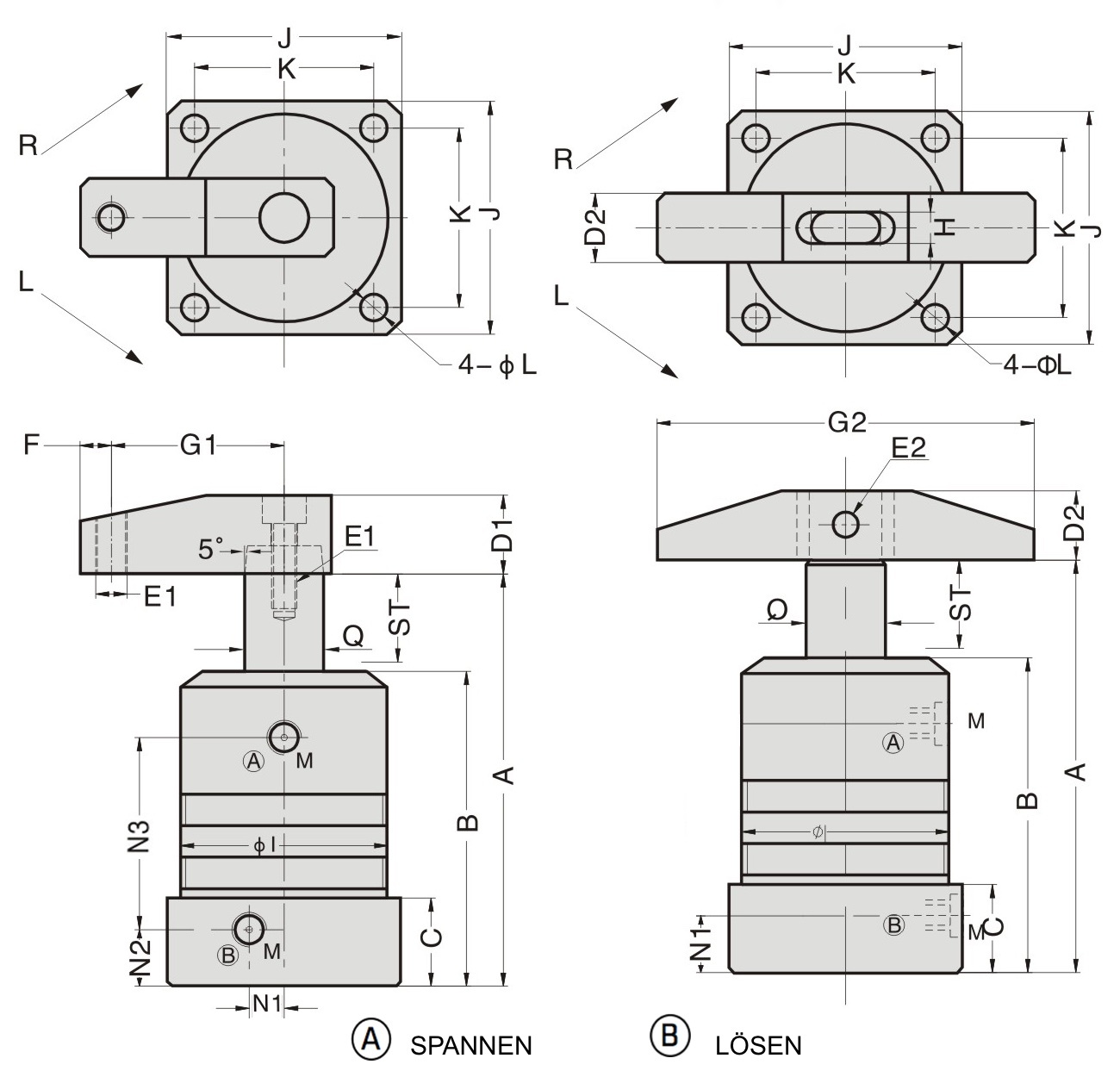
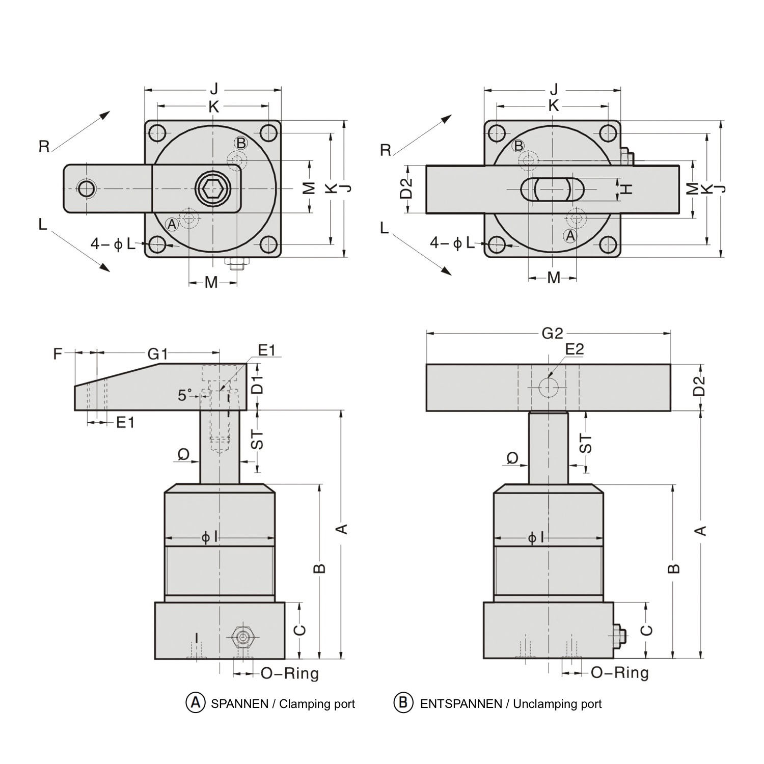
| Modell | PSC-25 | PSC-32 | PSC-40 | PSC-50 | PSC-63 |
|---|---|---|---|---|---|
| Total stroke | 24 | 24 | 24 | 28 | 30 |
| Swing stroke | 12 | 12 | 12 | 14 | 15 |
| Clamping stroke | 12 | 12 | 12 | 14 | 15 |
| A unclamped | 98 | 101.5 | 107 | 114.5 | 121 |
| B | 66.5 | 71 | 75 | 80 | 86.5 |
| C | 23 | 23 | 27 | 26 | 30 |
| D1 | 16 | 19 | 19 | 25 | 25 |
| D2 | 19 | 19 | 19 | 22 | 22 |
| E1 | M6 | M8 | M8 | M10 | M10 |
| E2 | Ø6 | Ø8 | Ø8 | Ø8 | Ø8 |
| F | 8 | 9 | 9 | 10 | 10 |
| G1 | 30 | 50 | 50 | 70 | 70 |
| G2 | 100 | 100 | 100 | 120 | 120 |
| H | 9 | 9 | 9 | 10 | 10 |
| ØI | Ø35 | Ø50 | Ø55 | Ø65 | Ø75 |
| J | 40 | 54 | 58 | 69 | 82 |
| K | 31 | 44 | 48 | 55 | 64 |
| L | Ø4.5 | Ø6.5 | Ø6.5 | Ø8.5 | Ø8.5 |
| M | M5 | PT1/8 | PT1/8 | PT1/8 | PT1/8 |
| N1 | 7.5 | 11.5 | 11 | 17 | 21.8 |
| N2 | 13 | 14.5 | 17 | 17.5 | 21 |
| N3 | 38 | 44.5 | 46 | 50.5 | 53 |
| Q | Ø14 | Ø16 | Ø16 | Ø20 | Ø20 |
| CAD S | D | a.A. | a.A. | a.A. | a.A. | a.A. |
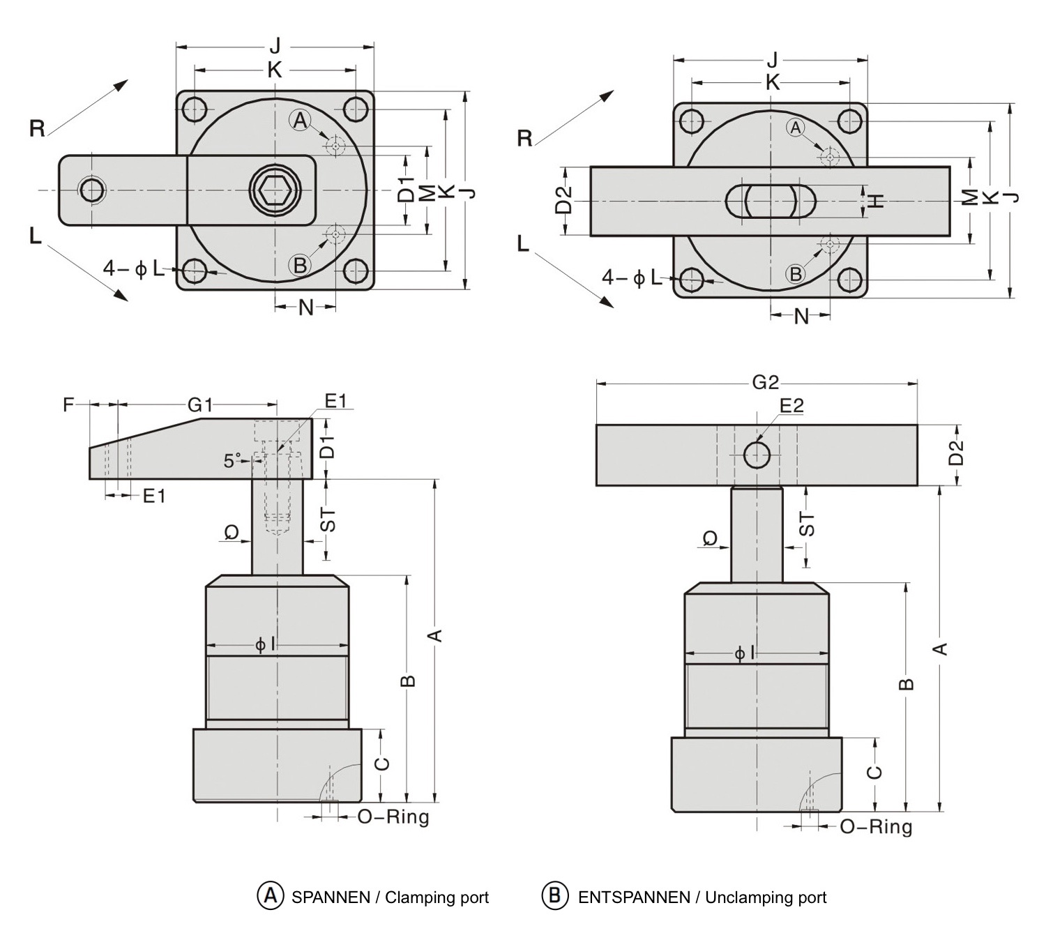
| Modell | PSC-M32 | PSC-M40 | PSC-M50 | PSC-M63 |
|---|---|---|---|---|
| Total stroke | 24 | 24 | 28 | 30 |
| Swing stroke | 12 | 12 | 14 | 15 |
| Clamping stroke | 12 | 12 | 14 | 15 |
| A unclamped | 101.5 | 107 | 114.5 | 121 |
| B | 71 | 75 | 80 | 86.5 |
| C | 23 | 27 | 26 | 30 |
| D1 | 19 | 19 | 25 | 25 |
| D2 | 19 | 19 | 22 | 22 |
| E1 | M8 | M8 | M10 | M10 |
| E2 | Ø8 | Ø8 | Ø8 | Ø8 |
| F | 9 | 9 | 10 | 10 |
| G1 | 50 | 50 | 70 | 70 |
| G2 | 100 | 100 | 120 | 120 |
| H | 9 | 9 | 10 | 10 |
| ØI | Ø50 | Ø55 | Ø65 | Ø75 |
| J | 54 | 58 | 69 | 82 |
| K | 44 | 48 | 55 | 64 |
| L | Ø6.5 | Ø6.5 | Ø8.5 | Ø8.5 |
| M | 24 | 26 | 30 | 40.5 |
| N | 16.5 | 20 | 25 | 28 |
| O-Ring | S4 | S3 | S3 | S4 |
| Q | Ø16 | Ø16 | Ø20 | Ø20 |
| CAD S | D | a.A. | a.A. | a.A. | a.A. |
| Modell | PSC-MF32 | PSC-MF40 | PSC-MF50 | PSC-MF63 |
|---|---|---|---|---|
| Total stroke | 24 | 24 | 28 | 30 |
| Swing stroke | 12 | 12 | 14 | 15 |
| Clamping stroke | 12 | 12 | 14 | 15 |
| A unclamped | 101.5 | 107 | 114.5 | 121 |
| B | 71 | 75 | 80 | 86.5 |
| C | 23 | 27 | 26 | 30 |
| D1 | 19 | 19 | 25 | 25 |
| D2 | 19 | 19 | 22 | 22 |
| E1 | M8 | M8 | M10 | M10 |
| E2 | Ø8 | Ø8 | Ø8 | Ø8 |
| F | 9 | 9 | 10 | 10 |
| G1 | 50 | 50 | 70 | 70 |
| G2 | 100 | 100 | 120 | 120 |
| H | 9 | 9 | 10 | 10 |
| ØI | Ø50 | Ø55 | Ø65 | Ø75 |
| J | 54 | 58 | 69 | 82 |
| K | 44 | 48 | 55 | 64 |
| L | Ø6.5 | Ø6.5 | Ø8.5 | Ø8.5 |
| M | 19 | 23 | 28 | 32 |
| Q | Ø16 | Ø16 | Ø20 | Ø20 |
| O-Ring | P7 | P7 | P9 | P9 |
| CAD S | D | a.A. | a.A. | a.A. | a.A. |
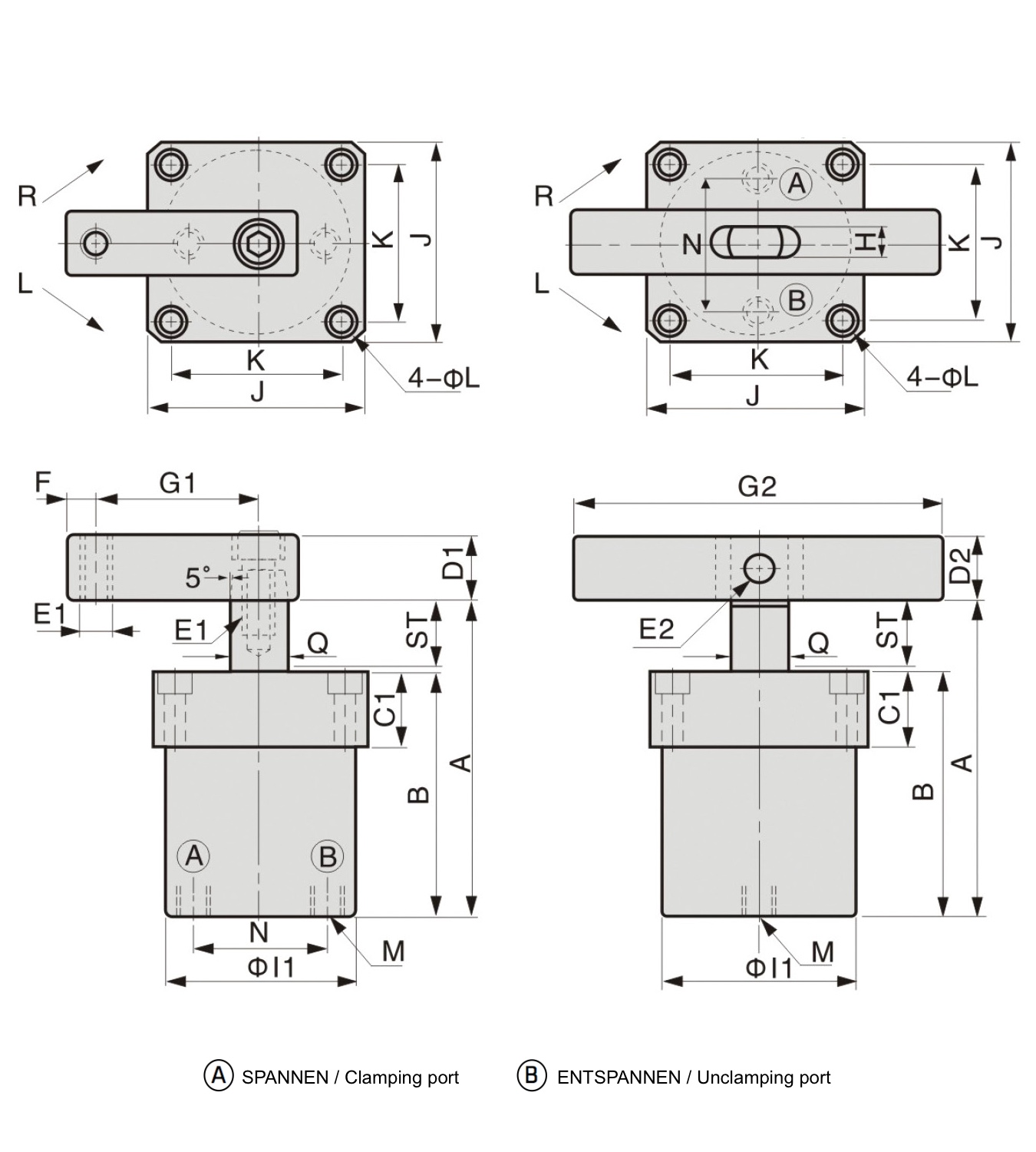
| Modell | PSC-FA32 | PSC-FA40 | PSC-FA50 | PSC-FA63 |
|---|---|---|---|---|
| Total stroke | 26 | 26 | 30 | 30 |
| Swing stroke | 11 | 11 | 13 | 13 |
| Clamping stroke | 15 | 15 | 17 | 17 |
| A unclamped | 108 | 108 | 124 | 124 |
| B | 78 | 78 | 90 | 90 |
| C1 | 22 | 22 | 25 | 25 |
| D1 | 19 | 19 | 25 | 25 |
| D2 | 19 | 19 | 22 | 22 |
| E1 | M8 | M8 | M10 | M10 |
| E2 | Ø8 | Ø8 | Ø8 | Ø8 |
| F | 9 | 9 | 10 | 10 |
| G1 | 50 | 50 | 70 | 70 |
| G2 | 100 | 100 | 120 | 120 |
| H | 9 | 9 | 10 | 10 |
| ØI1 | Ø50 | Ø55 | Ø65 | Ø75 |
| J | 54 | 60 | 69 | 82 |
| K | 44 | 48 | 55 | 64 |
| L | Ø5.6-Ø9 x5.5D |
Ø6.8-Ø10.5 x6.5D |
Ø6.8-Ø10.5 x6.5D |
Ø9-Ø14 x9D |
| M | PT1/8 | PT1/8 | PT1/8 | PT1/8 |
| M | 32 | 40 | 50 | 63 |
| Q | Ø16 | Ø16 | Ø20 | Ø20 |
| CAD S | D | a.A. | a.A. | a.A. | a.A. |
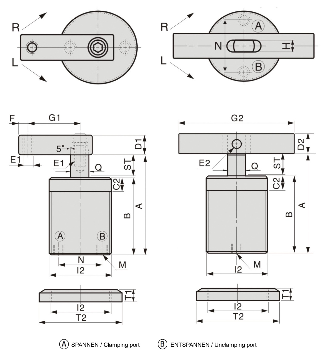
| Modell | PSC-TB32 | PSC-TB40 | PSC-TB50 |
|---|---|---|---|
| Total stroke | 26 | 26 | 30 |
| Swing stroke | 11 | 11 | 13 |
| Clamping stroke | 15 | 15 | 17 |
| A unclamped | 108 | 108 | 124 |
| B | 78 | 78 | 90 |
| C2 | 12 | 12 | 15 |
| D1 | 19 | 19 | 25 |
| D2 | 19 | 19 | 22 |
| E1 | M8 | M8 | M10 |
| E2 | Ø8 | Ø8 | Ø8 |
| F | 9 | 9 | 10 |
| G1 | 50 | 50 | 70 |
| G2 | 100 | 100 | 120 |
| H | 9 | 9 | 10 |
| ØI1 | Ø50 | Ø55 | Ø65 |
| I2 | M50x1.5 | M55x1.5 | M65.1.5 |
| M | PT1/8 | PT1/8 | PT1/8 |
| M | 32 | 40 | 50 |
| T1(2Stk.) | 11 | 11 | 12 |
| T2 | Ø70 | Ø75 | Ø85 |
| Q | Ø16 | Ø16 | Ø20 |
| CAD S | D | a.A. | a.A. | a.A. |