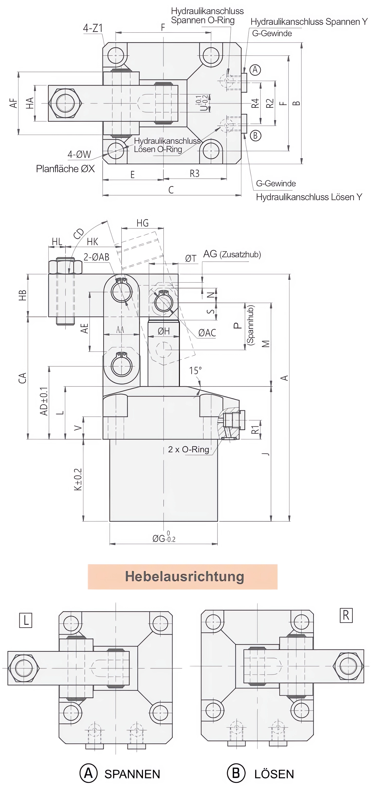
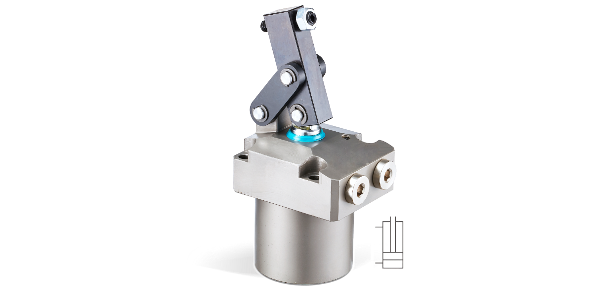
HLKP Hydraulic Link Clamp - double acting
Hdyraulic Link Clamp - Hydraulic Cylinder :
- very compact series with low flange design
- suitable especially for compact and light fixtures with high clamping forces.
- double acting type
- High clamping forces 2,7kN up to 31kN
- Clamping force depends on the clamp arm length and hydraulic pressure
- complete with clamping arm and screw
- Use flow control valve for meter-in control.
- Min. operating pressure : 10bar
- Max. operating pressure : 70bar
- Range of Temperature : -10 ~ +70°C
- various sizes and optional in manifold type with O-Ring (Y) or line type with G-port piping (G)
➝ CAD-files and prices on Request !
Ordering Indication:
HLKP - 040 R
Series – Size – Lever direction
| ① | SERIES | HLKP | |
| ② | Body size | 040 / 048 / 055 / 065 / 075 / 105 | |
| ③ | Lever direction | Blank: Standard front side (with G Thread Port) R: Right side L: Left side |
| Model | Clamping force at 70 bar | Clamping stroke | Total stroke | Oil capacity Clamp | Oil capacity Unclamp | eff. piston area clamp | eff. piston area unclamp | CAD |
|---|---|---|---|---|---|---|---|---|
| [kN] | [mm] | [mm] | [cm³] | [cm³] | [cm²] | [cm²] | ||
| HLKP-040 | 2,83 | 17,5 | 20,5 | 7,7 | 10 | 3,77 | 4,9 | |
| HLKP-048 | 3,91 | 20,5 | 23,5 | 13 | 16,7 | 5,56 | 7,1 | |
| HLKP-055 | 4,86 | 23 | 26 | 21 | 25 | 8,06 | 9,6 | |
| HLKP-065 | 8,14 | 26,5 | 29,5 | 38,9 | 44,8 | 13,2 | 15,2 | |
| HLKP-075 | 13,46 | 33 | 36 | 74,5 | 88,6 | 20,66 | 24,6 | |
| HLKP-105 | 20,20 | 42 | 45 | 145,5 | 173,3 | 32,35 | 38,5 |